The demand for PCB assembly based equipment has increased in recent years. These devices are used in every industry, from the military and defence to toys. This shows that we are becoming more dependent on PCBs. The use of these PCBs is possible only if certain criteria are met. Therefore, PCB manufacturers employ a number of PCB inspection techniques to ensure quality at various stages of manufacturing. It also helps in reducing the loss of good stuff, not just rejected projects. Want to know the different PCB test methods used by PCB manufacturers?
A brief discussion of the different types of PCB testing procedures used by PCB control companies
The demand for large digital devices is on the rise. This challenges PCB manufacturers to develop PCBs with comparable dimensions. These PCBs have many soldered connections that are not visible to the naked eye. With high level of communication, there is every possibility of discrepancies, misunderstandings, mistakes etc. Here these methods come to the rescue:
Available 3D Automated Optical Inspection tools allow manufacturers to verify accurate component height.
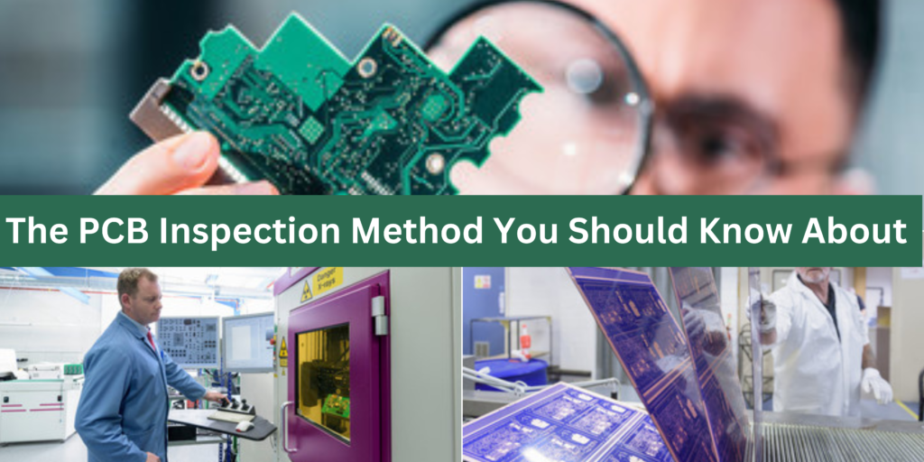
Automated Optical Inspection: This technique is often abbreviated as AOI. Printed circuit boards are scanned by high-resolution video cameras. The board is viewed from different angles and pictures are clicked by the cameras. These images can be mapped to create characteristics or gold tables to identify different faults. This method can be used to detect a variety of dimensional anomalies. This may include loose parts, lost or missing parts, etc.
X-ray Inspection: The demand for SMT (Surface Mount Technology) equipment is on the rise. Why? Because of these devices are small and heavy. As you know, there are over 25,000 links to solder circuit boards! Advances in SMT have increased the demand for microchip packages such as quad flat packages (QFPs), ultra-thin ball-gauge arrays (UBGAs), and smaller chip packages (0.2 mm pitch) where the bonding adhesive is not visible. These chip packages now have heavy duty solder joints and are inspected with X-ray equipment. Digital images of solder joints are produced using 256 grayscale X-rays.
Manual Inspection: This is the basic control method used by all small and large PCB manufacturers. This includes visual inspection of boards to locate major PCB problems. Although this technique is considered insufficient in some cases, it is still used by manufacturers.
Automated Laser Triangle (ALT) Measurement: As the name suggests, this technique uses laser technology to measure solder paste build-up or solder joint height. ALT test is mainly used to control solder paste printing. For example, it helps determine solder viscosity, solder quality, output board alignment, solder paste application pressure, breakdown rate, and leakage.
In addition to the PCB inspection methods mentioned above, there are different methods commonly used during the manufacturing phases. However, in some production phases, the search and location phases are performed later. Most advanced pick and place machines in use today are equipped with optical PCB inspection systems. These systems make it possible to reduce soldering defects and other manufacturing defect
Contact EITPL for PCB Assembly Services
PCB assembly is now more economical, more accurate and faster for automation. This enables PCB designers to obtain professional services in small and large order volumes in mass production. If you need PCB assembly services, contact one of our PCB experts.
Call us on +91 9910337896 or you can email us at info@eitpl.com and Whatsapp & Text +91 9650274009


